To facilitate the work of electricians, the isolation of cable products is subject to certain standards of color marking. When connecting a multicore cable by the color of the polymer sheath, you can identify the core and understand which contact it should be connected to.
Different colors of wires in the electrics, established by the provisions of GOST, help to accelerate the installation process and ensure electrical safety. Agree, an understanding of color coding is useful to every homemaster.
We offer you to understand the designations of electrical wiring, find out GOST standards and learn how to read letter codes of wires on diagrams. In addition, we will tell you how to check the correspondence of the connected core to its purpose using an indicator screwdriver or a multimeter.
What is said in GOST and PUE about color marking
The main document to rely on when manufacturing or purchasing cables is GOST 31947-2012. Before its appearance, there was no uniformity and order in the field of color designation of electrical wiring.
Until now, in old houses you can find wires in the same shell, the color of which does not determine whether it is connected - “phase”, “zero” or “earth”.

Now it is much easier to identify the veins. Even without the use of a tester, you can determine to which contact a particular core should be connected - by the color of the polymer insulation
The GOST document indicated above indicates that the insulation of cable products should be different in color. A certain shade should cover the wire in a continuous layer - from beginning to end. It is impossible for one wire at the beginning of the bay to be blue, and the end to white; intermittent coloring is also prohibited.

The only vein that can have a two-tone sheath is "earth." Officially, a green / yellow combination is assigned to it, separately these two shades can not be used
The regulatory documents also contain recommendations on the use of various schemes for 3-wire, 4-wire and 5-wire cables.
For example, in the manufacture of 3-core cables, the following combinations are welcome:
- brown - blue - green / yellow;
- brown - gray - black.
If the cable consists of 4 cores, then two typical painting options are also recommended:
- brown - gray - black - green / yellow;
- brown - gray - black - blue.
The schemes for a 5-wire wire are as follows:
- brown - gray - black - green / yellow - blue;
- brown - gray - 2 black - blue.
The blue color indicates the "zero" core.
It is not recommended to use only two colors - red and white.

There are special requirements for the color distribution of the grounding conductor: on any randomly selected piece of wire 1.5 cm long, one color should cover 30-70% of the insulation, the second color should cover the rest
The color should be applied firmly and be clearly distinguishable.
If you turn to the second important document for electricians - PUE, then in 1.1.1.29 and 1.1.1.30 you can also find information about the color of the phase-zero-ground wires. More precisely, the data are not written there, but there is a reference to GOST P 50462-92, which has long been replaced by the more recent edition of GOST R 50462-2009, which is valid today.
The material complies with the information set forth in GOST 31947, but there are some clarifications. For example, wires that perform a double function should be specially painted: if the zero worker is combined with the zero protective, then along the entire length it is painted in blue, and on the edges it has green-yellow stripes.

Schematic representation of the color marking of conductors. Along with the color designation, the cores have a letter: zero - N, protective - PE, combined zero + protective - PEN
Thus, all colors except blue (cyan) and green / yellow can be used to paint the insulation of the phase conductor. White and red colors fall into this group, which for some reason are not recommended for use by the 2012 state standard version of the edition.

An example of a three-core cable manufactured in accordance with GOST standards: a green / yellow core is intended for grounding, blue - zero, brown - phase
Appendix A to GOST R 50462 has a table in which you can find the letter designations of all colors. For example, the phase conductor of a 1-phase circuit (L) is brown, the color code is BN. Letter codes are used for black and white copies of schemes that do not use different colors.
Core marking for electrical solutions
No wonder at the beginning of the article the idea was voiced that the color designation of conductors greatly simplifies the installation process.
If you yourself are wiring electricians in an apartment or a private house, select the wires according to the standards, when connecting electrical devices, installing automatic protection, distributing the wires in the junction boxes, you do not need to double-check where the phase, zero, ground - the color of the insulation tells about this.
A few examples of wiring when labeling is important:
Image Gallery
Photo from
Connection lived in a distribution box
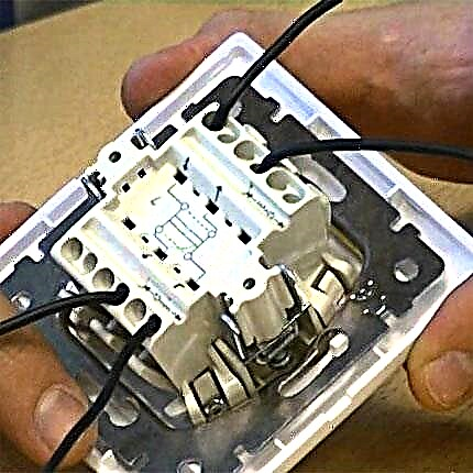
Installation of an electrical outlet
Connecting lines to machines
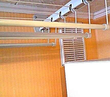
Installation of a chandelier or lamp
There are cables with a large number of cores, the coloring of which does not seem appropriate. An example is SIP, which uses a different method for determining conductors. One of them is marked with a small groove along its entire length. The relief vein usually performs the function of a zero conductor, the rest play the role of linear ones.
To distinguish the veins, they are marked with adhesive tape, heat shrink, letter designations, which are applied with multi-colored markers. And in the process of electrical work, they necessarily make a call - additional identification.
Checking the connection
Unfortunately, not all electricians strictly comply with the standards and, when connected, make mistakes in choosing a conductor. Therefore, when hanging a chandelier, installing a socket or other wiring device, it is better to additionally check whether the insulation of each core corresponds to its purpose.

A mandatory neutral or phase check is dictated by safety standards and the self-preservation instinct: if you accidentally mix the contacts during installation, you can get an unpleasant injury - an electric burn
For identification, installers use two methods: the first is using an indicator screwdriver, and the second is using a tester or multimeter. The phase is usually determined with a screwdriver, and neutral and zero are used with measuring instruments.
How to use the indicator?
Even simple devices like indicator screwdrivers are different. Some of them are equipped with a small button, others are triggered automatically when a metal rod and current-carrying core or contact are connected.
But in all models without exception, an LED is lit, ignited under voltage.

The indicator screwdriver is preferred to use by fans who do not have special qualifications. Professional electricians value accuracy, so they always have a tester with them
A screwdriver is a convenient tool for determining the phase conductor. To find out if the working core, the metal core of the screwdriver must be gently touch the exposed wire.
If the LED lights up, the core is energized. The absence of a signal indicates that it is ground or zero.

When using the indicator, you should adhere to the rules of TB. Even if the handle of the screwdriver is insulated, it is recommended to wear protective (with a rubberized inner layer) gloves, as when working with an electrician in general
The verification procedure is performed with one hand, therefore, the second is free. It is also better to use it - for example, to fix the wires. But it is strictly forbidden with the second hand to touch the exposed parts of conductors or metal objects located nearby (pipes, fittings).
Tester Application Rules
A tester or multimeter is always included with the electrician. He has to work with connecting the cores in electrical installations indoors and during the assembly of the electrical panel. If the wiring was mounted for a long time, the color marking of the wires can be neglected.
Even if the insulation colors seem to be sustained, it is not a fact that they are connected in accordance with all the rules.

Using the tester, you can find out not only the probability of connecting the conductors to the mains, but also some parameters: current strength, resistance, voltage. With a multimeter, you can ring diodes, check transistors, determine inductance
Before measurements, you should study the instructions that accompany all measuring instruments.
The procedure is approximately the following:
- we set a value that is obviously greater than the expected voltage, for example, 260 V;
- we connect probes in the necessary sockets;
- touch probes to two conductors - presumably phase and neutral;
- repeat the procedure with another pair of conductors.
The combination of phase-zero conductors should produce a result close to 220 V. It will always be higher than the phase-ground pair.
On sale there are both digital, modern devices, and obsolete, with arrows and scale values. Using digital is more convenient. Before self-installation of electrical devices, we recommend that you learn to use either an indicator screwdriver or a multimeter - you should not rely only on the color of the cores.
The ability to use a multimeter is useful to a home master and to check the voltage in the outlet. Detailed instructions for using the tester are given in this article.
Common Color Marking Standards:
Labeling methods in addition to color:
When all wires are the same color - check with a test lamp:
Color coding of conductors is a wonderful way to identify the wire during its installation. However, in the process of working with already installed cables, you should not rely only on the appearance of the conductors, since they can be connected erroneously.
Be sure to use additional methods for determining the conductors, and if you can not change the wires themselves, then you need to mark them with colored tape or letter symbols.
Have something to supplement, or have questions about color coding? You can leave comments on the publication, participate in discussions and share your own experience in identifying conductors. The contact form is located in the lower block.